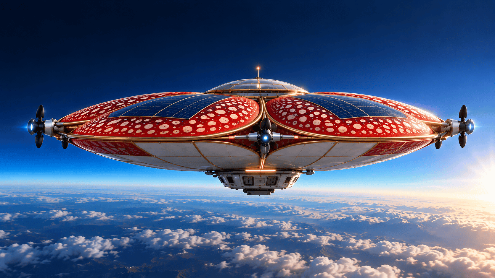
BUNGA ANGKASA
STRATOSPHERIC TELECOMMUNICATION STATION
Exploring the engineering feasibility of persistent, high-altitude telecommunications platforms through advanced airship architecture, autonomous flight control, and solar-electric energy systems.
A New Perspective on High-Altitude Connectivity
Persistent regional coverage bridging terrestrial towers and satellite constellations.
Stratospheric telecom airships are a feasible but challenging concept, recommended to be built as semi-rigid, helium-filled, solar-electric platforms operating at 18–25 km altitudes. While the stratosphere provides persistent regional coverage, the airships must manage extreme gas expansion as atmospheric pressure drops significantly. The hardest operational challenge is station-keeping against winds, which requires an autonomous flight controller and an energy budget capable of surviving worst-case nighttime conditions on battery power. For safety and continuous telecom coverage, operators must rely on fleet-level health monitoring to seamlessly launch replacement airships before initiating a controlled descent for the original platforms.
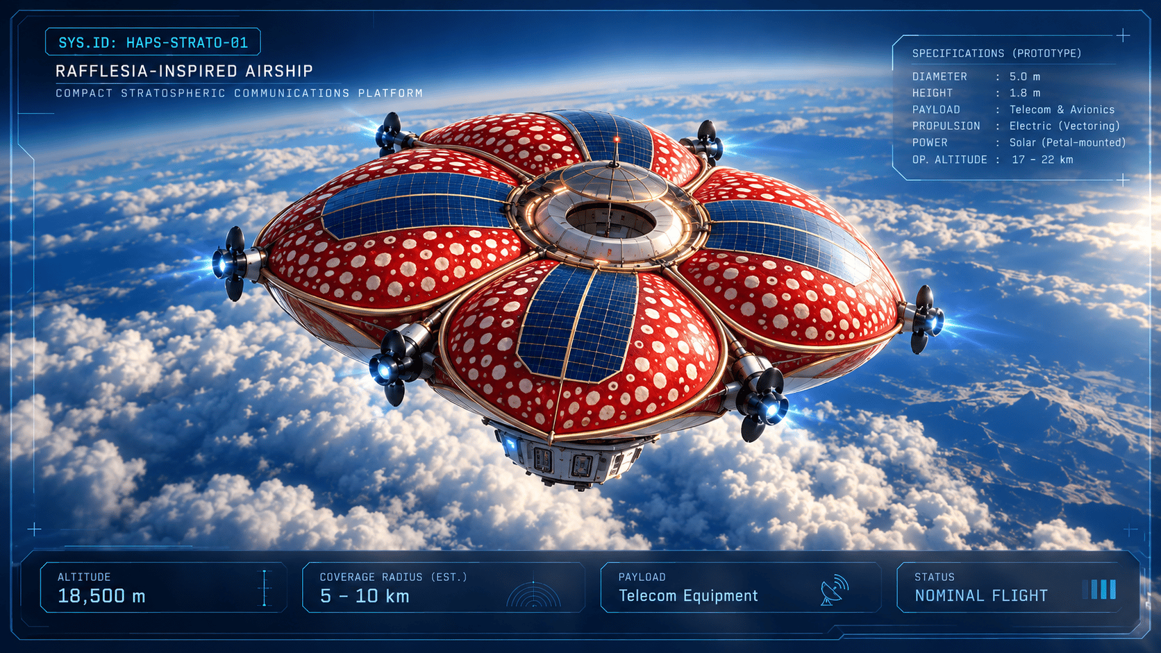
Why the Stratosphere?
Comparing the operating physics and trade-offs of the stratosphere versus Low Earth Orbit.
STRATOSPHERE
Aerostatic High-Altitude Platform
- Aerostatic lift in atmosphere (buoyancy provides passive vertical support)
- Persistent over a regional footprint (no fast orbital transit across sky)
- Wind drives propulsion demand (dynamic vector thrust required)
- Recoverable, serviceable platform (can be landed, upgraded, and redeployed)
- Low path loss (~20 km propagation allows standard user device connection)
LOW EARTH ORBIT (LEO)
Satellite Constellation
- Orbital free-fall; no buoyant lift (requires orbital insertion velocity ~7.8 km/s)
- Constellation handover required (satellites cross horizon in minutes)
- No aerodynamic station-keeping (vacuum environment, atmospheric drag minimal)
- Large footprint; significantly higher path loss and latency
- Disposal or uncontrolled orbital decay; unserviceable once launched
Choosing the Right Airship Architecture
Evaluating structural mass, fabrication complexity, and payload integration across three configurations.
NON-RIGID
Envelope carries shape
- Lowest structural dry mass
- Simple fabrication and transport
- Limited scale and shape authority
- Concentrated load stress directly on flexible hull fabric
Suboptimal for heavy high-altitude station-keeping propulsion and large antennas.
SEMI-RIGID
Keel + pressurized envelope
- Balanced structural mass and stiffness
- Dedicated structural keel payload load path
- Distributes propulsion thrust and battery mass efficiently
- Strong baseline candidate for early demonstrators
RECOMMENDED BASELINE — Optimal balance of stiffness, mass penalty, and payload mounting.
RIGID
Internal frame + gas cells
- Scales to very large internal gas volume
- Distributed independent gas cells for redundancy
- Highest complexity, fabrication cost, and baseline structural mass
- Structural deadweight severely restricts stratospheric payload capacity
High deadweight penalty makes closure difficult at 20 km stratospheric air densities.
Structural Selection Rationale: A semi-rigid keel offers a dedicated mechanical load path to mount distributed electric thrusters, payload antennas, and battery masses without causing localized fabric stress concentrations, while preserving the low structural weight needed for high stratospheric buoyancy.
Helium vs Hydrogen
Gross lift capability versus operational and safety constraints.
Helium
Inert Noble Gas
- Inert, non-flammable lifting gas
- Zero combustion risk during launch, ground handling, and flight
- Scarce and costly supply chain
- Preferred for early flight test and prototype validation
Hydrogen
High-Efficiency Lift Candidate
- ~8% more gross lift than helium
- Abundant, low-cost green production potential
- Flammable gas with wide explosive flammability limits
- Requires rigorous explosion-proof zoning, purging, and safety clearance
*Illustrative ISA sea-level values. Net useful lift depends on altitude, temperature, envelope mass and pressure.
Engineering the Lift
Buoyancy: First Sizing Gate
Volume of a tri-axial ellipsoid representing the streamlined hull geometry. Where a = 60m, and b = c = 15m.
Advanced Envelope & Gas Cell Engineering
A four-layer laminated composite engineered to withstand the extreme stratospheric environment.
UV & Ozone Resistant Outer Coating
Protects the structural substrate and gas barrier from high UV flux, aggressive monatomic oxygen, and ozone degradation at 20 km.
MANUFACTURING VALIDATION
Helium Permeation Testing
Biaxial Tensile Testing
Tear Resistance
Seam Strength
Thermal Cycling
Accelerated Weathering
Leak Testing of Completed Hull
Pressure Control & Altitude Stability
Balancing the 14-fold volumetric expansion of lifting gas from sea level to the stratosphere.
System Architecture Accommodations
Gas Expansion
Controlled increase in helium-cell volume with altitude as ambient pressure decreases.
Ballonets (Air Chambers)
Adjustable internal air bladders filled or emptied by electric blowers to manage internal pressure, hull rigidity, and aerodynamic trim.
Pressure Regulation
Active overpressure relief valves and pressure transducers prevent catastrophic hull rupture during ascent or envelope collapse during descent.
Thermal Management
Accommodating intense solar superheating by day (increasing pressure) and radiative cooling at night.
Altitude Control
Coordinated management of aerostatic buoyancy, ballonet air mass, dynamic aerodynamic lift, and thrust vectoring.
The Hardest Engineering Challenge
Overcoming horizontal stratospheric winds with limited solar-electric energy reserves.
Aerodynamic Drag: D ∝ v² | Required Power: P ∝ v³
Aerodynamic drag rises roughly with v²; required propulsive power rises near v³. A modest seasonal wind increase can rapidly overwhelm the vehicle's daily energy budget.
Buoyancy controls vertical support passively without energy consumption.
Horizontal wind constantly attempts to displace the airship from its target station.
Forecast
Ingest stratospheric atmospheric winds and synoptic jet stream models.
Choose Altitude
Ascend or descend within 18–25 km to locate minimal wind velocity layers.
Vector Thrust
Actuate multi-axis electric propellers to counter current wind vectors.
Monitor Energy
Continuously check battery state of charge (SoC) against night duration.
Preserve Safe Corridor
Ensure vehicle remains firmly within civil-designated geofenced station.
Intelligent Station-Keeping Control
A closed-loop avionics architecture integrating multi-source navigation and predictive control.
Ground control and target coordinates
Defines permitted operating position and flight limits
Navigation and wind estimation
GNSS + INS + atmospheric forecasts + onboard sensors
Autonomous flight controller
Calculates steering, thrust and altitude corrections.
Powering Persistent Flight
Harvesting solar energy by day to power multi-night station-keeping survival.
Resilience by Design
A four-layer safety architecture designed to prevent catastrophic loss of lift and maintain mission continuity.
Layered Mechanism to Counter the Problem
Continuous Health Monitoring
Monitor gas inventory or inferred leakage, cell pressure, temperature, envelope strain, altitude, battery state, propulsion health and position error.
Preserve Buoyancy and Operating Margin
Use low-permeability materials, qualified seams, appropriate gas-cell compartmentation, pressure control and sufficient design margin. Carry reserve gas only if its mass budget is justified.
Fleet-Level Continuity
A ground operations system predicts failures, dispatches a replacement, coordinates telecom handover and confirms that the replacement is ready before the original platform leaves service.
Safe Return
If the platform becomes unsafe, execute a predefined contingency: protect the payload, maintain essential control power, descend to an approved recovery area and alert airspace authorities as required.
From Research to Demonstration
A phased development methodology advancing through five rigorous technical gates.